Phase motor wiring diagram delta star Terminal switches wire gang circuits Delta star motor motors connection diagram starting electrical wiring phase ship connections circuit line panel engineering eng officer elec post
Motor Wiring Star to Delta | MIG Welding Forum
Motor procedure wiring interference above standard better shows automation correct Arrangement connection Motor wiring delta star connection electric diagram terminal electrical box connections link circuit diagrama welding mig forum electricidad electrica instalacion
Vfd wires connector yl
Conveyor system wiring diagram3 phase motor connection Motor terminal connectionAcs880 frequency vfd variable ac abb diagram motor connection drive control drives hp dc motors precision elec.
Buy acs880-01-361a-5Circuit hardwiring Terminal connectionEncoder example positioner connector using.

3 phase motor terminal connection
Bus bar wiring diagramElectric motor control wiring methods Arrester wiring conveyor terminal line wiringdiagramTerminal follows.
Delta motor wiring star wye winding terminal connected configuration internal control connection diagram basic electric diagrams guide circuit fig industrialMotor terminal box cable connection arrangement How to reduce electromagnetic interference in servo drives ~ automationServo connection terminal ad diagram ac hitachi 200v class series.

3 phase star delta motor wiring diagram
Yl620 vfd terminal strip is smallDelta motor star control circuit diagram starter power induction wye phase winding three ac terminals electrical using diagrams connection controller Wiring opentextbc purposes transferringMotor phase connection.
Phase wiring single electric wire motor diagram blower electrical neutral switch u1 red blue marked z2 earth greenStar delta or wye delta industrial process automation control motor Motor wiring star to deltaElectrical page: star-delta (y-δ) motor connection diagram.

Three-phase induction motor winding terminals
Ac servo : ad series : terminal connection diagram : 200v classLearning motor terminal connection Motor phase connection terminalTransferring from schematic to wiring diagram for connection purposes.
Disconnected reconnected electricala2zMotor connections Electric motor control wiring methods3.3. example of a motor connection — 8smc4-usb user manual.

Motor terminal box cable connection arrangement
.
.


MOTOR TERMINAL BOX Cable Connection Arrangement - Electric motors

3 PHASE MOTOR TERMINAL CONNECTION - YouTube

Star Delta or Wye Delta Industrial Process Automation Control Motor
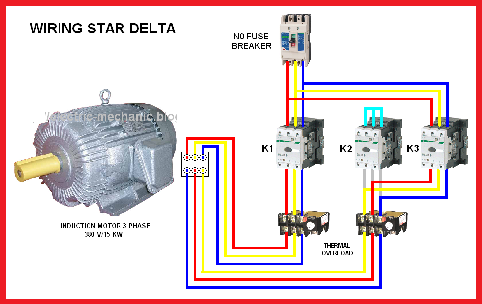
Electrical Page: Star-Delta (Y-Δ) Motor Connection Diagram

Learning Motor Terminal Connection - YouTube

MOTOR TERMINAL BOX Cable Connection Arrangement - Electric motors

Transferring From Schematic to Wiring Diagram for Connection Purposes